Case Study · structdevice · Digital P&R

Chat Case Study: Wiring a Custom Device into a Digital Flow, All the Way to LVS Match

Three requests, three real tool-driven stages: fit a custom device's exemplar geometry into a parametric PCell, place and route it from a netlist, then run live LVS to confirm the layout matches the netlist exactly.

This is a real chat transcript. Every user request below is the kind of thing a real user would say; for each one, klink's AI agent actually drove the full fit → place → route → LVS pipeline against a live, running KLayout -- the screenshots and the LVS match / device count are the actual results of this run.
User
I have the same device drawn at a few different sizes (exemplar geometry) -- can you fit that into one PCell I can re-parameterize freely?
klink agent

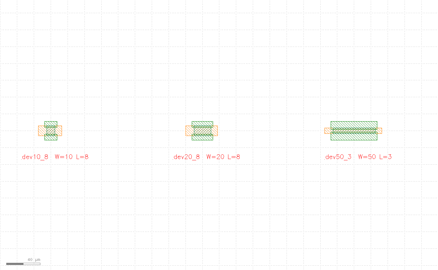
Running a fit screening over your 4 exemplar sizes (a synthetic back-gate device, W=10/50 µm × L=4/8 µm, both parameters varied independently): every role edge gets a linear regression against the parameters and is classified linear (parameter-driven), constant (doesn't move), or unexplained (the fitter can't explain it -- your call). The screening came back clean, so I built the fit table and registered it as a real PCell (demobg), then drew 3 variants to prove the parametrization is real: dev10_8 is the exemplar point itself, dev20_8 interpolates along W, and dev50_3 extrapolates along L (outside the exemplar range).
pcell_fitter.analyze(exemplars=4, params=["w_um","l_um"]) → edges: 14 linear, 2 constant, 0 unexplained (all 16 edges explained) pcell_fitter.fit_table(report, style="default", sample_order=[...]) pcell.register_fitted(name="demobg", fit_table=...) instance.insert_pcell_many(cell, [ dev10_8(w_um=10, l_um=8), # exemplar point dev20_8(w_um=20, l_um=8), # interpolation dev50_3(w_um=50, l_um=3), # extrapolation ])
Three device variants drawn from the same PCell, dev10_8, dev20_8, dev50_3, each a different size, with an orange gate plate, green source/drain, and a hatched channel
Turn 1 · Three instances of the same demobg PCell at three parameter sets. The fit screening found 14 of 16 edges linear, 2 constant, and 0 unexplained -- the parametrization is fitted, not hard-coded.
User
Place these devices from a small netlist, and route them in detail.
klink agent

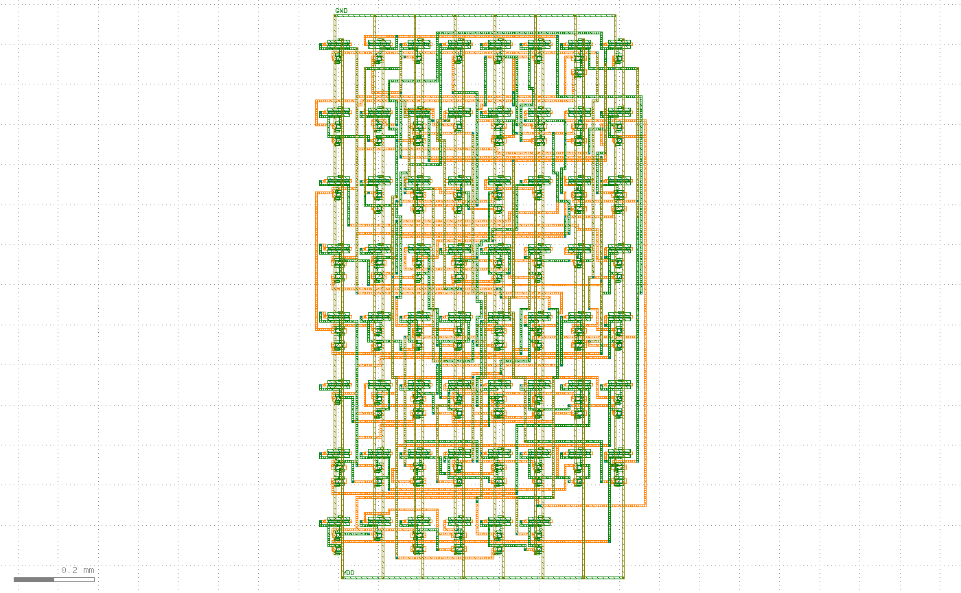
The netlist is a bundled 4-bit adder (62 gates, 173 device instances, 96 nets). The row/column count and row pitch aren't guessed -- they're derived from the netlist itself: 62 gates → an 8×8 grid, row pitch = device stack height + routing channel, worked out to 170 µm. After batch-placing all 173 fitted PCell instances, the signal nets among those 96 go to the FlexDR detailed router on a 3-layer stack; VDD/GND ride the power grid separately, outside the "signal net" count.
routing.grid.floorplan.derive_grid(gates=62) → rows=8, cols=8 routing.grid.floorplan.derive_row_pitch(...) → row_pitch_um=170.0 structdevice.layout_engine.place_grid(nl, rows=8, cols=8, profile, row_pitch) → 173 device instances instance.insert_pcell_many(cell, 173 items) structdevice.layout_engine.route_and_draw_flexdr(cell, nl, placement, profile, layers=3, ...) → FlexDR 3.9s ok=True routed=94/94 markers=0 sig_vias=200 pdn_vias=166
Fully routed 8x8 device array: green horizontal traces and orange/grey vertical traces fill the row channels, with a power ring around the whole array labeled GND at top and VDD at bottom
Turn 2 · All 173 instances placed, 94 of 94 signal nets routed, 0 DRC violations (markers=0). The power ring (GND/VDD) runs 166 PDN vias; the signal nets add another 200 cross-layer vias.
User
Run LVS to confirm the drawn layout's connectivity matches the netlist exactly.
klink agent

Not "looks connected" -- KLayout's native connectivity extractor is the judge: it extracts nets from the real geometry just drawn (metal-layer connectivity + via crossings), reconciles them one by one against the 96 nets declared in step two, then does a device-level netlist comparison across all 173 devices. The extractor's connectivity rules are derived from the same profile the router used, but the extraction itself is KLayout's native engine -- not the router grading its own work. The real result gets written back onto the layout so it's easy to check by eye:

structdevice.lvs_check(cell, declared=96 nets, mode="lvsdb", connectivity=profile.connectivity_spec(), terminal_provider=geom_terminal_provider(...), placement=..., device_terms=...) → ok=True → device_lvs.match=True → device_lvs.device_count=173 shape.insert_text(cell, "LVS match=True devices=173", layer=6/0)

Real result: match=True, all 173 devices reconciled -- the connectivity drawn in the layout matches the declared netlist exactly.
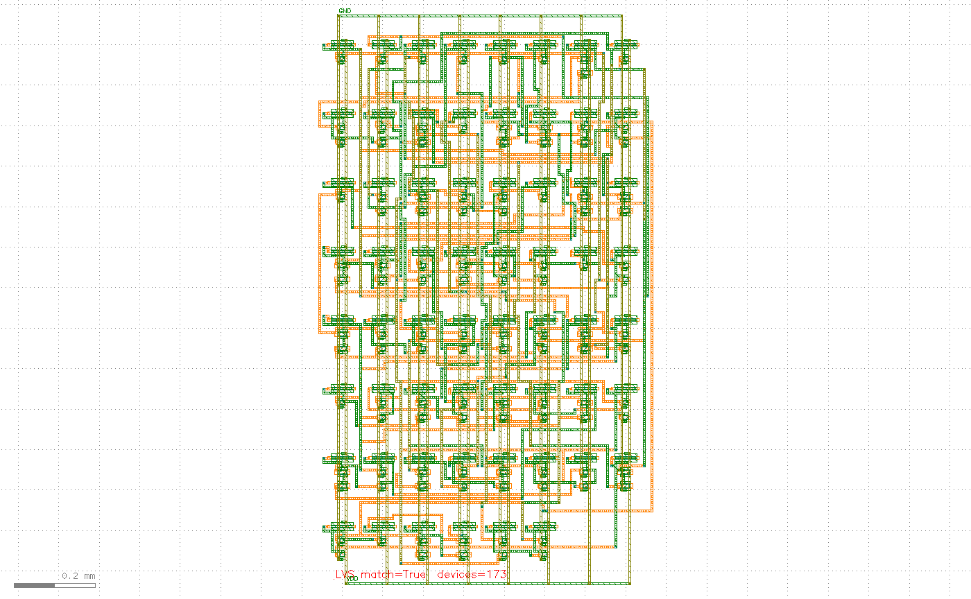
Overview of the finished 4-bit adder layout with red text at the bottom reading LVS match=True devices=173
Turn 3 · The finished layout after LVS passes. The red text is the actual result written back by the agent -- LVS match=True devices=173 -- placed at the layout's real bounding box, not pre-staged decoration.

Want the full step-by-step version with the fit formulas and zoomed-in detail shots? See the custom device tutorial. Full DRC/LVS capability → Guide · DRC · LVS.

Honest recap: the device geometry, layer numbers (101/0 gate plate, 103/0 channel, 104/0 source/drain, 106/0 routing, 6/0 annotation text), and 4-bit adder netlist on this page are all synthesized/bundled demo data with no real process or customer content; the fit/place/route/LVS calls and their reported numbers (14 linear + 2 constant edges, routed=94/94, markers=0, LVS match=True, devices=173) were all executed for real against a live KLayout (dedicated session, port 8767), and the screenshots are the actual render output of that run. The disposable tab used for this work was closed at the end and the original tab restored as the active view; no session on 8765/8766 was touched.